When I was in college, I interned with a great German industrial automation company. I specifically remember that the programming environment we sold to customers included support for "condition-coil" logic, AKA "ladder logic." Basically just simulated relays.
For controls guys who had dealt with relays for most of their professional lives, that relay-oriented logic flow made sense. A typical computer science student's idea of boolean logic gates and procedural control flow just wasn't part of their lexicon.
We also offered a graphical, procedural programming language (imagine Scratch except it controls part of a factory). You could teach it to them, and they'd understand it, but many of them never used it. They just wanted relays.
> I specifically remember that the programming environment we sold to customers included support for "condition-coil" logic, AKA "ladder logic."
Yes, the IEC 61131 languages. AWL is a crippled assembler language, ST is a crippled Pascal.
Industrial automation is for masochists. The usual explanation is that the PLCs need to be programmed by electricians without any college degree, but (a) are electricians not stupid and (b) would better languages not need to be more complicated.
It was so much worse before 61131. My career in industrial automation was on PLCs that predate 61131's existence and had no structured text language of any kind. Ladder only. I helped write a toolchain that compiles languages similar to 61131 (but, again, predating it) down to ladder. I've seen an implementation of bitwise floating-point math in ladder that no mortal human could possibly understand.
Our experience was not that companies think electricians are stupid, but that they're electricians: they know electrical stuff, not computer programming. A ladder diagram is immediately recognizable to an electrician or technician who needs to diagnose an equipment failure and wasn't involved in writing the program.
61131! I haven't thought about that number in years. Couldn't agree with your evaluation more. The sad thing about ST is that it was probably the least shitty of the IEC 61131 languages.
Despite the masochism, it was a fun field to work in for a time. Since the industry demands these shitty esoteric programming languages, you end up with all these small companies writing their own compilers and runtimes. It's a unique opportunity to do real-life compiler development from the ground up.
61131 has ladder logic, function block, and structured text, which is a pretty eclectic group of programming representations. I think about 99% of the PLC programs I saw were ladder logic, with the exceptions being Siemens pushing structured text with a C-like look-and-feel.
Anywho, cool, robust, reliable things still got made, you just had to think differently. It was very interesting to think about those programs and their relative programming simplicity when compared to complex, modern C++ that is running in other codebases I've seen since then.
I wonder what a better language would look like. It would have to be similarly locked down, because trusting a programmer with a full strength language seems like a bad idea when it's something that could kill people if it fails.
For anyone interested in trying out ladder logic, I run a web app that includes a ladder logic simulator in the browser. There is a small set of lessons too.
Sorry it’s desktop only for now. I never got around to figuring out how to make the drag and drop interface work well on mobile screens, although I’d love to.
> For controls guys who had dealt with relays for most of their professional lives, that relay-oriented logic flow made sense.
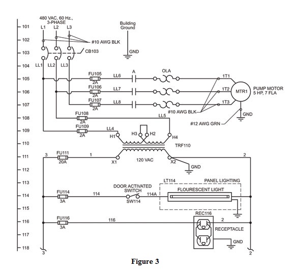
Ladder logic is based on ladder control schematics. They were used for machine control circuits to present the circuit as a series of rungs running from left to right, the left side representing a connection to the control power supply hot or positive line and the right represented the control power supply return or negative. Each rung is a circuit that handles some logic. eg you have a laser machine with three doors and two access panels each holding a normally open switch closed to complete the circuit - when all the doors are closed the output is signal is high which you can use to ensure the doors are closed so no one gets melted. The sequence reads top to bottom so when you trouble shoot you walk down the steps checking each right hand output device and if it didn't work, work your ways backwards through the rung with a volt meter.
Way back I got to fix an old Marvell power feed metal cutting band saw. All relay logic and the saw would run one cycle, retract and do nothing. So I grabbed a meter and the ladder diagram and worked my way down until I found a rung with no output. Turns out the saw carriage return limit switch bracket came loose and the return switch was never pressed which would reset another rung to restart the cycle again.
> A typical computer science student's idea of boolean logic gates and procedural control flow just wasn't part of their lexicon.
Nonsense. I was exposed to industrial automation in high school where I was preparing to become an electrician via a robotic manufacturing system from eshed robotec. I really liked computers but was never interested in programming them at that point even though I knew some gw basic and the robots were programmed in basic. Then I wound up taking an AP c++ programming class and it clicked.
To me ladder is a great language and perfect for representing the boolean data flow through sensors and switches to visually group functions into rungs. It's so much faster to visually parse a rung vs a block of text. It's the default on every controller for a reason.
Though I'll say this: automation software sucks shit through a straw. So much of it was designed on Windows while riding the 90s OOP hype train. And the design by committee with languages and standards baked into iec/iso standards is depressing. 61131-3 defines a crappy Pascal like language called "structured text" but everyone bolts on their own oop extensions to the language in various proprietary ways. And you don't want to begin to fuck with the absolute dog shit Byzantine garbage fires that are PLC IDEs. They're so invasive that everyone in the biz runs then in VMs so they don't bork the OS.
Another thing to note is that, depending on the standards (e.g. NFPA vs IEC), your control diagrams would be in horizontal [0] or vertical [1] format. So the typical left-right ladder flow you might see in RSLogix or something worked really well with drawings produced to NFPA standards, but the mapping broke when given "waterfall"-like schematics from a European shop.
You are 100% correct about the tooling being crap and ladder representation being useful as a visual mapping.
Ladder is completely unknown in most of Europe. I think it's mostly ST (structured text) followed by fbd (function block diagram) or sfc (sequential flow chart).
I'm not against st or c or whatever, I've done control programs in all of them. To me, Debugging ladder is awesome as most IDEs give you a live view of the io state and it's great to sit the laptop or computer cart by the machine and begin pressing switches and wiggling wiring/connectors to see what is not working and the ladder contacts light up when they go high. Simple fast visual debugging.
We've incorporated some flow chart and ladder like io debug screens on our hmi's. Pop open the debug screen and see what isn't on and the association of inputs and the output condition they set. Mostly eliminates the need to drag around the computer.
I was in my mid 20's when I was sent by my company to give a short training course to a civilian group that worked for the US Army Signal Corps at Fort Gordon. These guys built simulators of the big field radios that the signalmen carried around and everything was done with relay logic. This was the mid 90's and it blew my mind: I'd heard of relay logic in some EE course or the other, but I'd never actually seen it in operation. It's one thing to understand what's theoretically possible; quite another to actually see combinatorial and timing logic executed by loudly clacking relays. But it worked!
They used relay logic because it's what they knew: some of them had backgrounds in industrial control. The small company I worked for sold single board computers and the group leader knew that there had to be a better, more modern method of building their simulators, so they asked to have someone sent down to educate them. That someone was me. I probably did a piss-poor job of it (no experience or aptitude for training at the time) but I hope it at least set them on the right path.
I had the good fortune to go inside a Pac Bell switch. Inside was an entire floor of 2-post relay racks housing… wait for it… relays. The click clacking was music to my ears. Phone system switching predated transistors and computers.
Weren’t early MIT based SWE also model railroaders? I think there is some connection there between model railroad switching, relays and logic.
lcamtuf, or as I like to call him "imposter syndrome as a service" (that's not totally fair; I've caught up to him in many ways over the past few years).
Now that I know what a relay is, I can't unhear it. When I plug in my EV for charging, I hear the solid click of a (probably quite large) relay. When my coffee maker cycles on or off, I hear a relay. I don't particularly like it.
In an EV charger, it's more likely to be a contactor, which is similar to a relay but can better deal with high amounts of current. (Technology Connections has a video on the differences https://youtu.be/VsNHrAzx5_w)
If you want more household relays to notice, it's common to find them in digital thermostats for central HVAC control signaling. I've also found them inside of ovens, and cars also have lots of them for things like the starter and headlights (although maybe not the latter in newer cars.)
Relays and contractors are the same.
It's a coil physically movin some contacts together to allow current to flow.
I got no idea why, where or how the naming came about or who decides.
But i guess its the same as creeks and rivers, when does a creek become a river
I'd say they're physically different, but logically the same. They're both a coil that moves some contacts to make or break a current path, but a contactor has physical differences which allow it to break much higher current. Contactors have features to ensure the arc resulting from breaking the connection can be extinguished, relays just assume no significant arc will form in the first place.
It's like the difference between a pickup truck with a ball hitch & a class 8 semi-truck with a fifth wheel coupling for a 53' trailer. Both are just vehicles that tow a trailer, but the physical details of how they do that are different in important ways.
I hadn't heard of contactor but that looks like it's just a subtype of relay? And I notice that it says contactors are used where relays start to top out, around 15A. Which is interesting because the max current I can configure my RAV4 Prime to is ... 14A. Either way I'm not opening up the little portable box that makes this noise. It's clear there's something physical clacking in there, not solid state.
Yes, the big deal with contactors is that they're designed to switch high-current inductive loads. Smaller relays may have problems with the arcing caused by a load like a motor welding the contacts together.
So, they have bigger contacts to handle the current and strong springs and a powerful solenoid to open/close the contacts quickly and extinguish an arc before it has time to melt anything.
The noise you're hearing is from the contacts opening and closing.
I follow lcamtuf on Mastodon and I am convinced he's made of different stuff than I am. A full-time job is enough for me, I can't imagine starting (and completing) so many cool side projects. To that point, right before this relay madness, he wrote up an article in a playable embedded Tetris clone: <https://lcamtuf.substack.com/p/mcu-land-part-10-blocks-all-t...>.
No small 100nF capacitors. Only a bulk 1uF and 10uF capacitor inches away. Very inefficient layout. Is that just a 10 Ohm resistor connected to a physical switch to control the backlight? DC-DC module? He's got a PCB on there already, it shouldn't be that much harder to slap down a Buck converter himself.
What size components are those? Far larger than 0805, they might actually be like 2012 (inch) components.
Good grief. I guess Microchip / Atmel chips are legendary for this reason: they always were considered braindead easy to boot. But this is the higher-end Cortex-M7 series chips, I'd imagine that you'd need at least a _bit_ more care with regards to decoupling and power-delivery to achieve reliability than what he did here!
No seriously. A 300MHz processor with _NO_ local decoupling capacitors? Is he mad?
------------
But then again, I guess there's something to be said about making a board "easier" and through less effort. I guess there's no reason to be a masochist with 0603 (or smaller) parts when prototyping.
He's upgraded to the SAMS70 which is 300MHz. Its a totally different class of processor.
> Also the device worked even when it was on a breadboard, suggesting he made reasonable technical decisions regarding placebo capacitors.
I dunno. PDN (power-delivery network) issues are really complex. You solve a lot of headaches with a 1-penny 100nF capacitor here and there.
I'm very curious what the SAMS70's onboard capacitance is. I'm wondering if Microchip/Atmel goes overboard on onboard capacitance or something.
In any case: the documentation from Microchip is clear about this. 100nF capacitors on every input pin. I don't see any reason to stray from this, its not like 100nF capacitors are expensive, or even difficult to solder.
Are you looking at the same thing? There clearly are decoupling caps not far from the chip. There's no rule to say you need to use 10 x 100 nF capacitors in 0603. They are more cost-efficient, but they're more work to solder by hand.
The DC-DC module also seems like a sensible choice for hand assembly. These things cost about a buck or two these days.
This board is clearly meant to display the electronic components in plain view and be easy to solder at home.
> There's no rule to say you need to use 10x 0603 100 nF capacitors.
The Microchip documentation for the SAMS70 literally recommends 15x 100nF capacitors, as well as a 4.7uF capacitor for the buck converter, and a second 4.7uF bulk decoupling capacitor.
That's 17x capacitors if you're just following the manufacturer's recommendation.
The board as shown in that blog has ZERO of them. Madness. Each 100nF capacitor "should" be directly adjacent to the power-pin its decoupling, fractions of a mm away. And to make sure there's enough room for everything to go on (fractions of a mm is very small), you want to use 0603, or 0402, or smaller parts just for convenience.
But 0603 is already troublesome for hand-placing IMO. (though the even smaller 0402 is still possible in my experience). So as I said, it starts to get masochistic with these sizes IMO. But still, I'd personally try to get at least a decoupling capacitor on each power-pin as the documents recommend (even if its a larger 0805 or bigger).
In any case, the ~4 capacitors that he places is very much on the low-end compared to the ~17 recommended.
-------------
> They are more cost-efficient, but they're more work to solder by hand.
These are all surface mount parts, which means you're soldering using frying-pan and/or toaster-oven at this point.
Or at least, you _SHOULD_ be doing that (or maybe get a real hotplate, lol. But my pancake electric griddle works perfect). Its way more convenient.
You apply the solder paste. Then you drop the capacitor into place with tweezers, and the solder-paste is sticky enough to "grab" the capacitor. You then place all other components. Easy-peasy.
Heat the entire board to 330F (assuming low-melt lead-free solder) using the frying pan for 10-seconds and done. Some people like adding a 1/4" aluminum plate to make the heat more consistently applied.
Components are designed for 500F for 10 seconds btw (aka: standard lead-free solder). So you have a lot of leeway with regards to the frying pan method in practice. But you should keep a strict timer as some parts are really sensitive to that "for 10 seconds" requirement. A proper reflow oven and/or hotplate obviously does the job better with automatic controls, but this is all slow enough that you can do it by hand by just turning the dial up/down with a stopwatch in your hands.
You should assume that lcamtuf knows literally everything you've said here and more, and made his decision thoughtfully, and the result worked as expected.
Bimetallic strips are pretty slow, I can't imagine them being audible. I'd guess what you're hearing is almost certainly a relay, very likely driven by the bimetallic strip
edit: Replies have pointed out that they sometimes do "snap", so i guess i'm wrong there. I'm still pretty sure anything in a kettle/coffee pot/toaster etc would be a relay to avoid arcing
It's totally possible to shape a bimetallic strip in a way that makes it bistable, thus clicking between the two states, just like an electrical switch which uses springs inside which are normally not noisy either.
One construction I've seen is with a permanent magnet for hysteresis; the strip jumps to the magnet when it gets close, and then requires extra tension to release. The thermostat in my first apartment worked this way (and it looked to me like the strip was actually carrying the current to operate the gas heater; presumably a NC valve).
A bimetallic strip making a noise when it flexes is the origin of the original blinker noise. Cars these days just emulate the sound, but that’s where it came from.
It depends on the kind: a lot of bimetallic strips are designed to have hysteresis, so they snap to a different shape at one temperature and then stay like that until the cool down further (at which point they snap back), and this can produce a click.
I've opened up my water kettle before and it uses a little bimetalic strip to shut itself off once the water is boiling. According to the label it sucks 1500 watts and it's just shoving mains voltage through the heating coil.
Interesting; I always thought of bimetallic strips as being continuous, and silent. I'd open the machine up but unfortunately, it's my production coffee maker and the users would not be happy if there was downtime.
I opened it up, causing a production outage that was noticed by the users.
Anyway, the relevant part seems to be a Univen T250 XB thermostat, but I can't figure out what the technology inside is.
When I was small, my parents got me a Fischertechnik kit that included relays. I still remember the day I discovered that by hooking the output of a relay to its input, one could either produce stable or instable (cf the Y combinator?) behaviour, and the latter produced a relay clicking like mad, as fast as its time constants allowed it...
Bonus points for mechanically tuning the relay to give you the highest frequency possible. A little screw set into the top of the relay casing that pushes down on the arm can make the relay substantially quicker (at the price of some more contact bounce but that's fine).
Oooh, flashback to early TRS-80 days - there was an on-motherboard relay to control the tapedeck (pause/continue transport, you still had to have the buttons pushed down.) You could instead drive it fast enough to make (very grating) tones, probably damaging it over time (your limiting factor was "everyone in earshot trying to make you stop", by "grating" I mean "small metal box full of bees" :-)
4PDT relays might seem exotic now, but they are quite common when you're working on old radios, etc. As for carrying through complementary signals, that's a good hack.
There is a type of logic using Micromachined Silicon cantilever switches, operated by static voltages, capable of operation for sustained periods. They don't seem to have achieved fully non-volatile operation, but you can spend a lot of money to have a relay of this type, if you want.[1]
At one point I was hopeful this would replace relay logic, and be even lower power than CMOS.
I have an 8bit relay cpu with 4k word code memory and 256 register file with banking, this thing clocks at about 20 hz and my main problem is looking (and not finding) for interesting stuff what I can code on this thing. Even a simple snake game with 8x8 dot display is painfully slow, tetris will be unplayable. What else? Calculator? A 16bit multiplication runs longer that I can count in my head :/
The point of using relays was for the sound. Reed relays dont make loud enough clack and going solid state is pointless, you can go directly with transistors then. Regarding more info I am very lazy at doing writups and schematics are all hand drawn, so its highly unlikely I will ever publish anything about it. It has 280 relays, based off two clocks with 4 phases (typical latch design from 80s), 12 bit PC, 8 bit ACC, zero and carry flags, immediate, direct and indirect adressing modes. Loud, noisy and totally useless. Memory interface is emulated via attached MCU
Posting about this looks like easy karma. I understand that writing about the projects takes a lot of time, but if you ever have time to do it, my guess is that it will be well received here. (Remember to include a video. The first thing I did in the current post was to play the video the heard the clicks.)
Yes, there are two memory IF, one for program (12 addr, 16 data) and one for data (8 bit addr, 8 data) and this is directly attached to an IO board where MCU emulates both rom/ram chips. Additionally, MCU interprets the code and checks for expected signals. The added bonus is that you can easily add memory mapped io, i.e dot matrix display and mcu intercepts reads/writes to certain adresses and makes an action (ie toggle led, halt, or switch page)
Also just so nobody misses it in the description, there's a whole page with many photos and an additional 1 hour video going into more details than the video on YouTube: http://web.cecs.pdx.edu/~harry/Relay/index.html
Wow, I essentially did this same project a number of years ago, but never finished it. My ship ran aground debugging division since it becomes long and convoluted to do it, especially when also dealing with negative numbers and decimals.
I also added an LED board that was an array of LEDs, one LED per relay, attached to it's coil. This way you could see the states of the calculator flash by as it computed, akin to those old blinking button boards of retro sci-fi. Really neat project!
I especially like that it has some relay outputs so you can short basically any electrical item, possibly even an AC mains cable :) and it has numerous inputs and LED display of the internal program counter. I even spent a few hours making a simple drum machine in it once!
When I was younger straight out of college I designed a digital clock that was relay-based. I made a 0-16 counter circuit on one board and a 10-reset circuit on another board. I didn't have 4 pole relays, just 2 pole, but I did try to make use of a mix of normally open (N.O.) and normally closed (N.C.) to keep the parts count low. The binary-to-7 segment logic was to be implemented using a diode ROM.
I had the same idea about using clear relays--so you could see the parts working, but I couldn't find those at the local electrics shop, so I instead just took the plastic housings off of standard relays.
If you think this is fun you might enjoy MHRD - a game about building a gradually building up to functioning CPU using only logic gates (i.e. transistors/relays).
You can have all the puzzley fun of it without any soldering etc.
Slightly off topic, but would anyone know how to make PCB routing look smooth and curved like that? The screenshot looks like it's the 3D KiCad viz, but KiCad doesn't have that functionality by default.
I would add: don't do that in KiCad. Although they added the functionality, it's clear that they never really QA'd it. It's profoundly broken. Many simple shapes are impossible to achieve, adjustments are painful and often require redrawing the entire track, selection boxes are not calculated correctly so you end up accidentally selecting curved tracks that are inches away...
If you want to design boards with curved traces, paying several hundred bucks for DipTrace is almost certainly a better route.