I've had an idea that I've been pinning to build for a while. I call it "the anachronism clock". The time piece is an old fashion pendulum. This is used to generate regular electrical pulses via point contacts. This signal would go to a series of electro-mechanical counters based on drums, motors, point contacts, and regions of non-conductivity. The counters would be arranged to output their position to mock nixie tubes built from LED's and plexiglass. Once an hour a tape recorder would be activated which will play a recording of the chimes of big ben.
Coming at it from the other side, not too hard to make a long-case ('grandfather') clock using the per-second signal from MSF (WWV, DCF etc) to drive the pendulum and so lock the clock to 'atomic' time.
An old 6 volt relay coil worked for me, main issue is needing a local backup oscillator stable enough to cope with period of signal loss/power outages.
Obviously simpler to use GPS 1PPS to derive the drive signal but that's a challenge to pick up with a coil of wire and a capacitor.
Definitely could be done; you'd also need an electromagnet to "pulse" the pendulum (much like the magnetic "perpetual motion" toys out there).
Also - I would suggest using regular bulbs instead of LEDs. If you can deal with the higher voltages involved, neon lamps would give it a great look.
Also, rather than a tape recorder, use one of those large doorbell "big ben" chimes instead (if you can find a really old one - from the 1960s or so - some of them used a similar motor/drum switched sequencer for the solenoid chime playing system).
It sounds very intriguing, and probably would be cool to watch function...
Another idea: synthesize a 32.768 kHz clock signal from the 1 PPS pulse of the pendulum by PLL, and use this clock to power a modern microcontroller to drive the 7-segment LEDs and show the current time.
That is really cool. I also liked "The Clock", a 24hr film montage with every scene showing a clock with the correct time. I didn't see much of it but it was mesmerising to watch.
It could be a 12V AC adapter. Not too common, but they do exist. Four of the myriad diodes would be connected in a bridge rectifier to convert the AC to DC. (I don't see any smoothing capacitors though....)
Depending on how creative you wanted to get, a clock might be designed to run directly on a pulsating rectified DC supply. That would give you a sort of baseband embedded clock signal at 120 Hz. Or use two half-wave rectifiers and design the whole clock based on trinary logic, +12V/0/-12V.
Realistically, since the mains connection is hidden behind the frame, it would be easy to tap off internally a connection to the 12V AC signal from the secondary of the transformer, before it gets rectified and filtered to DC.
Awesome, btw I did not think you would need so much discrete components to do that, but probably the conversion of the counter to the digits segments is the majority of it.
It looks like DTL (diode-transistor logic) is being used; if implemented properly, quite a few parts are needed for just a NAND gate, and a BCD decoder uses a lot of them.
That said, counters aren't lightweight in that arena either...
That's a time piece I would call a piece of modern art, here "art" being used in the most direct and non-ironic sense, as it was used in Renaissanse times.
Makes me wonder, why not use decimal counters? If designed cleverly enough, they could drive the segments directly.
Each digit would have 7 latches, one for each segment, and cycle through just 10 of the otherwise possible 128 states. It would be ironic to use clockless logic, making simpler latches.
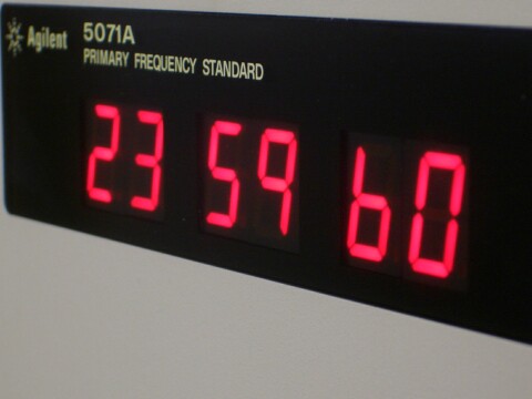
5071A does leap seconds (http://leapsecond.com/notes/5071a-leapsecond.jpg) and IIRC even can do timezones and DST (although that seems like a feature of somewhat questionable utility). Whether you want to call such an device a "clock" is another issue ;)
Why are there so many diodes? There totally seem to be more than necessary... Are you biasing transistors with diodes? That doesn't sound like it's going to work well as temperature changes...