As devices like home fridges move towards “inverter drive” with switch mode power supplies, I wonder how low of a voltage they could still run off. And if they’d happily accept 48VDC and still function.
Saw a teardown/repair of a big home flatscreen TV and while the label on the outside said “120VAC”, the power supply inside said 120/240V, so it was the same internals worldwide, but labelled differently to discourage gray-market imports.
> As devices like home fridges move towards “inverter drive” with switch mode power supplies, I wonder how low of a voltage they could still run off. And if they’d happily accept 48VDC and still function.
The technical side should continue to work until you reach the lower limit of what the bootstrap circuitry can handle.
The problem will be the amperages required... say, a fridge. Its motor will run at ~200 watts, which means 1A at 230V. No biggie. But if you're going down to 48V, the high-voltage side will now run 4A, and more the lower you go on voltage - and that's without taking peak inrush currents into account which can easily go to 10A@230V (or 40A@48V) for a few split seconds. If your current source or the wiring can't hold that, you'll likely run into serious issues.
Inrush current is much less of an issue with a VFD/inverter driven motor then a motor controlled by a basic DOL motor starter. ABB claims that the inrush current of their VFDs is 100-150% of the motor FLA, which lines up nicely with the NEC rule to size motor conductors at 125% of the FLA of the motor. A typical DOL/across the line starter has an inrush current 6-7x higher than the FLA.
I thought one major advantage of inverter drives was the well-managed starting currents. This is a noise/vibration advantage but also an electrical win.
It could have just been that one team labeled the housing according to the requirements, and another team built the internals to meet (or exceed) the requirements.
2) What conditions equipment went through testing under, as per regulatory regimes
Equipment I worked on needed to be tested for a variety of failure modes (e.g. a power supply doesn't cause a house fire), EMI/EMC, and so on. I would guess that also varies internationally, as well as by use (UL-listing is not legally required, but it is required if you sell to customers who want to have fire insurance, for example).
Some of this is wonky administrative overhead, but some of it is not. For example:
- A DC-DC converter will have a different switching frequency if running from a different input voltage. This might work fine, but it will have a very different profile for EMI/EMC. Testing that might be $40k. If I know I have a 12V wall wart powering it, there's no reason to spend $40k to be able to label the box "5V-40V."
- If a PCB has creepage / clearance for 120V, even if the power supply works fine for 240V, I can't sell it as 120V equipment. The reverse holds true the other way for wire gauge.
These things wouldn't cause problems very often (indeed, it'd be exceptionally rare), but if we have a house fire 0.001% of the time people bought a TV set, we'd have hundreds of thousands of preventable house fires. That's why there's testing before products are sold.
Just looking at a random AC/DC converter (Meanwell EPP-100) the likes of which from it and other brands that I’ve used many of, it specifies 90-264V AC at 47-63 Hz. Interestingly it does also specify 127-370VDC, but nothing on the data sheet specifies that it should be expected to operate with DC input (and that corresponds as a peak value to the RMS AC voltage which is probably what it means).
Potentially it could work with a DC input though (since DC will pass a regular bridge rectifier), but it could screw with things like the power factor correction… I’d try it if it was a unit I didn’t mind potentially destroying.
If they only assumed AC, and if they used AC coupling for the sine/peak/phase detection, then DC would probably look closer to 0V, and just shut the switching off, right?
I can't think of an "easy" way to do it that wouldn't require extra smarts, to handle DC, and everyone knows smarts costs money!
I recall someone stating rather authoritatively that they were confident that the WRT54G could comfortably run directly off of automotive "12 volt" DC power, which in practice can go up to 16 volts due to the alternator.
This person has a thesis that it can go up to 20 volts (which is 80% of the rating of one of the capacitors)
Automotive power has lots of very high spikes (>100V), it's definitely not recommended to connect electronics to it without a large amount of filtering and protection.
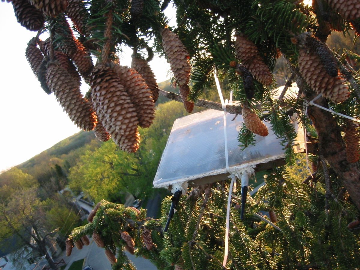
Yep, I did manually injected PoE on the extra ethernet pairs and soldered directly to the wrt54g board to put my router 70ft up in the pine tree next to my house. I powered it with 13.8v from a ham radio psu and it worked great. It was almost certainly less than 12v after the voltage drop from the run. I never did measure though, it just worked (for years).
As the article goes into, it drops everything down to 5V (or less) on the board. So as long as you’re getting like 7V (possibly as low as 4.75V per the article) to the board, you’re good.
I put everything in an oven pan then used a LCD screen diffusor panel for the top. I drilled holes in the side of the pan and sealed them with caulk. I did eventually get some water ingress from daily pressure/temp changes + humidity and significant rusting of the bottom of the pan but the elevated wrt54g was operational (if a bit nasty looking) when I took it out after 3 years. If I did it again I'd add some weep/drainage holes to mitigate build up.
If you're looking to connect a DC-powered device to a standards-based power-over-Ethernet switch without making any device modifications look up "PoE splitters". They're really, really handy devices. You can get them with USB connections and barrel plugs. I've gotten a lot of mileage out of them over the years.
First, I think it would be a great idea for any future Single Board Computer or Router designer -- to design their product such that it will work with any power supply from 5V to 12V (assuming that the power supply can provide enough amperes at that voltage).
Even better might be to design a SBC or Router such that it works with say, a minimum 500 milliamps at 5V -- which should make it compatible with just about any consumer power supply out there...
Yes, I know this is wishful thinking for several reasons. But let's look at the WRT54G & WRT54GS -- apparently these will work a power supply providing any voltage from 5V to 15V -- so long as it provides enough amperage at that voltage...
To be able to accomplish this is a great design practice for Routers, SBC's, and other small computing devices.
Also interesting: Look at the table of input voltages, supply current and watts.
Note that Watts, in general, goes down (not by a lot, and not at every voltage, but generally, linearly) as Voltage goes up...
That's an interesting effect...
If the article is correct, then this seems to be the work of the "integrated 150kHz step-down switching regulator".
I think it would be highly interesting (at least, if you are a SBC and/or Router manufacturer) to test all available step-down switching regulators -- and craft similar tables of input volts, amps and watts -- over the regulators' range of voltages. (Octopart anyone? https://octopart.com/)
Which regulator produces the best response over the range of voltages it handles, and then, go an extra step -- research and discover WHY that is, what are the reasons in Physics --
for the phenomenon?
I think that that would be a highly interesting endeavor!
(And of course, I'm also open to any suggestions for webpages for people who have already done this, or something like this!)
> ...Router designer ... to design their product such that it will work with any power supply from 5V to 12V...
I am one of those who often makes purchase decisions around the internal power circuitry.
I'm not at my lab desk at the moment (so I cannot report on that stuff), but I'm dragging around an old laptop, a small SBC (used as a general-purpose computer) and a monitor that I was employing earlier in cramped quarters for 40 minutes or so. The laptop is happy with 11.5V but doesn't have problems with 11-18V (9V 600mA will still charge the battery, slowly, during very mild use). The SBC has an NB679 buck converter so it's good for 5.5-28V. The monitor (2200 nits baby!) will accept 7-24V. These are older kit I use for crawling around with, but most of my "normal" equipment likewise has large input tolerances.
Non-normal equipment (used for areas at home where tool loss/damage may occur) mentioned: OLPC XO-1 (great screen, kinda tough, freakin' old), FriendlyElec NanoPC-T4 SBC, FeelGood P7 field monitor (compact with a thick aluminum chassis).
USB-C Mac laptops will happily take power at seemingly any voltage in the spec. Can plug in a USB-A -> USB-C cable and it will charge overnight at 5V1A, or at least increase endurance during operation. 9V, 12V, 15V, 20V, all good too. I wonder if it will accept anything in-between as well... it should? And where it tops out. Solar panel rigged to a USB-C cable anyone?
With ooooolder laptops, I found, as you did, that it's happy to take 12V and buck down everything, but can't boost and wouldn't charge at all. I sometimes use "incompatible" power bricks with a modern Dell laptop and they sometimes top-out of where they'll charge. Probably expecting 20V but getting 16V and not enough to get the cells topped up.
Made the mistake of thinking that same modern Dell laptop would take in 5V over USB-C to charge overnight like the MacBook... it did not.
It sounds like you would enjoy a career in electrical engineering. Most undergraduate EE curriculum will offer a class (usually both an undergraduate level and a graduate level version that covers more advanced typologies) specifically dedicated to answering the questions you are asking.
> Note that Watts, in general, goes down (not by a lot, and not at every voltage, but generally, linearly) as Voltage goes up...
I would say it flattens out pretty quickly and doesn't keep going linearly. This probably has to do with the fact that the device was designed to be powered from 12V so the supporting components of the power supply would have been chosen to maximize efficiency around that input voltage.
EDIT: I was curious and had a WRT54G v2.2 laying around (unlike the 1.0 used by OP), which results in this graph: https://i.imgur.com/CBNTtRI.png
The lower power usage can probably be explained by my later revision having less LEDs and more integrated chips instead of several discrete ones.
First, I think it would be a great idea for any future Single Board Computer or Router designer -- to design their product such that it will work with any power supply from 5V to 12V (assuming that the power supply can provide enough amperes at that voltage).
The chip in question is likely the 3.3 volt variant of the regulator chip. Looking at the data sheet[1], it can be made variable with a voltage divider. (Provided you disconnect the rest of the circuit, of course)
The physics of step down converters are well known, they've been around for a very long time.
This “higher input voltage is more efficient” can also happen with bridge/protection diodes. (E.g. devices that accept AC or DC, or any polarity of DC, or at least safely refuse to function if you plug in a barrel connector with the wrong polarity)
They’ll cause a fixed voltage drop, so the higher the voltage you put in, the lower the proportion of your power you lose.
240V computer power supplies are a bit more efficient than 120V ones because of this.
Apple made a big deal about the switching-mode power supply that was used in the Apple ][ computers, although this author thinks that they were over-hyping their contributions to the technology a bit.
> That means that the lower limit of the supply voltage is about 5V but the upper limit is much less than 40V. That's because the input capacitor is rated at 25V, so I would not suggest running it on more than 20V.
Depends on the type of capacitor but I probably wouldn’t push that past 14-16V, often for ceramics we’ll derate by 50% (specify a capacitor with at least double the voltage rating it will see) since capacitance can drop as voltage increases, depending on the temperature also. Electrolytics (which this looks like) should be fine for 60% or a little more, but 80% as the article suggests is pushing it!
People treat electrolytics more gently than their manufacturers intend. Voltage up to and even a bit beyond their rating doesn't bother them; you only need to leave margin for surges/spikes. If not for those, they are usually happy at 100% of rated voltage indefinitely.
What kills them is heat. No matter what the source is, internal heating must be managed if they're going to live. (They might still live a very long time, if they're high-end ones.) That means designing carefully around ripple currents. Ceramics in parallel can work magic here.
Now that source/supply and sink/drain/device are usb-c, it seems like this kind of flexibility would be possible for a huge number of systems.
It'd be interesting for systems to expose their efficiency curves, to make these kind of decisions optimally. Maybe your charger is much more efficient at 20v that the power efficient optimal solution is to pipe 20V in, even at low power modes. There's all kinds of optimization problems we could tweak, if this sort of efficiency data were visible.
Sure but that doesn't take into account charger efficiency.
Something designed to output 5V-48V might be quite inefficient at generating an asked for 6.65V, perhaps. Optimizing just for the device might be missing gobs of energy efficiency that could easily be found with a little testing & discovery.
There's decent odds that a good PPS implementation on the device - one that can directly connect the supply and battery without having to do intermediary conversions - is the most efficient option. PPS probably is the best choice. But it's not guaranteed. And particularly as we create higher power higher voltage capable chargers, their optimization point might be tuned to much bigger outputs (where they will absolutely require that efficiency to keep cool enough under load). Losses from running your charger sub-optimally could dwarf losses from the device receiving power sub-optimally for it.
The point seems to hold: we need data to know what the best option to do is. This submission showed one way of DIY'ing that data, but devices could also do better jobs self-reporting, which would let everyone tune better.
> That means that the lower limit of the supply voltage is about 5V but the upper limit is much less than 40V. That's because the input capacitor is rated at 25V, so I would not suggest running it on more than 20V.
Even that will stretch it without rework. The higher the voltage difference, the higher the heat losses - at the minimum you'll need a heatsink, at higher voltages I'd even go for active ventilation.
Yeah, I think they’ve mixed up linear regulators and buck converters. Buck converters are often more efficient with a larger voltage drop because the switch can run with a lower duty cycle.
Thanks, I never knew why. All I knew is whenever I need a buck converter in my DIY, novice PCBs, I just toss in an off-the-shelf preassembled one, with a small LDO on my actual PCB to drop the last bit and smooth it out.
The problem is the voltage drop. The bigger voltage difference it has to handle, the hotter it gets as its the loss from "internal loss current x voltage drop" is converted into hat.
The heat has to come from the input power though. If I'm pumping 5W at 12V, or 5W at 20V into the device, with it idling, presumably the output from the devices voltage regulator circuit is the same voltage, and the downstream components are consuming the same wattage (let's call it 1A at 3.3V downstream, so 3.3W), the both the 12V and the 20V input would have 1.7W of heat-loss. The article shows that as voltage goes up, power actually drops, which would imply that it is producing less heat.
Saw a teardown/repair of a big home flatscreen TV and while the label on the outside said “120VAC”, the power supply inside said 120/240V, so it was the same internals worldwide, but labelled differently to discourage gray-market imports.