Even if you're a "computer person" who is comfortable messing with the internals of a PC, be very careful with the power supply. Opening it up should really be left to professionals. Capacitors can remain charged for a long time after disconnecting the power cord. If despite all the warnings, you open it up to fiddle with internals because you think you understand the components and can pay attention not to touch things, at the very least, use only one hand at a time to avoid creating a circuit through your heart.
In most other parts of the computer the worst that can happen in most cases is that you damage the computer, the power supply is different, there you also have a good chance of getting shocked.
This happened to me as a young teenager. I tried to figure out which part of the power supply was broken. The case was opened, I measured some parts, connected it, turned it on and tested if it was working again and disconnected it before continuing to work. After the fourth time, I forgot to disconnect it before touching something with both hands. Fortunately, the GFCI was working as intended, but the cramp in my arms and a very strange feeling around my heart is something I will never forget.
So, to add another advice, be sure that you have a ground fault circuit interrupter or residual-current device and test it regularly.
Question for any medical professionals around: If you experience a substantial electrical shock, but it didn’t cause you to go into cardiac arrest and you don’t have any severe burns, is it likely that the danger is over? Or should you still seek medical attention as soon as possible?
If you receive a shock, if can affect the rhythm of your heart and cause problems later. We’re taught to go and get an ECG after receiving a shock. Like jump in the car and go to the doctor or hospital and have someone else drive you.
If you’ve received a shock - go get checked out.
Are you part of a union, and is this recommendation feasible because of "worker's compensation"? I imagine I might not go get checked out if I felt like the risk was low enough and I was worried enough about being able to pay the bill.
It is certainly a known fact that electrical shock can lead to death even hours after the event occured, which is why there is a legal requirement in most industrial nations with a working healthcare system that you get yourself checked even if you are feeling good.
Your heart muscle is controlled by a tiny voltage. Suddenly forcing it to follow 50/60Hz of a huge voltage isn't precisely natural, and something that can leave lasting damage even if your heart seems to work just fine immidiately after.
There is a reason in electrics a lot is done just to prevent electrical shocks (e.g. RCDs), because you know: it kills people.
I am legally allowed to connect houses to the electrical grid in Germany.
I have experienced some shocks from ground loops, where the shock was only perceptible when the current density was small enough. If I placed my whole palm on the conductor, I couldn't feel it, but if I placed just my finger tip on the edge, I could.
That was an electrical shock that in my naive opinion does not pose a cardiac risk.
I imagine that there is some judgement call to make about what is "electrical shock", and when does it pose a cardiac risk.
If all is going well, shocks are rare, and so I could imagine as a rule "if you felt a shock, go to the doctor". But in some [yes, of course, unfortunate, avoidable, and unacceptable] contexts, a rule like that might not be followed. That is why I was wondering about what guidance electrician's unions provide.
I am sorry for you if you live in a country where you have to chose between paying the bills or making sure you won’t end up in cardiac arrest because of something that happens as a part of your job. It hasn’t got anything to do with unions, it is basic respect for human life.
I received some electrical safety training even though I'm a software engineer and was told the same thing. An electric shock can lead to cardiac arrest for hours after it happened, with no prior warning. You should always see a cardiologist even if you feel completely fine. Without an ECG you can't know the risk.
>An electric shock can lead to cardiac arrest for hours after it happened, with no prior warning.
That's common in the way shark bites and lightening strikes are common. Dropping dead hours after a minor electrical shock is so rare you shouldn't even be worrying about it.
>You should always see a cardiologist even if you feel completely fine.
It was included in your training so the company could cover its ass. By including a comically over the top warning and recommendation like that they are ensuring that statistically nobody will follow the training and the company will have leverage if you get hurt on their watch and sue.
It's a really shame that this kind of disingenuous ass covering behavior gets picked up and parroted by people as though it were honest advice because it moves the overton window and leads to a world where everyone acts like step-stools are a serious threat to public health.
A friend who still works at that company has seen two minor electrical accidents during his career so far. An ambulance was naturally called and copious amounts of paperwork filled out. Workplace procedures were adapted so that such accidents will be less likely in the future.
Everybody follows the training, because you get fired if you don't, or your manager gets fired. I don't know where you live, but here we have unions that make sure workers are as safe as reasonably possible.
Am medical professional, if you receive a substantial electrical shock you should seek medical attention ASAP. There is the potential for a lethal arrhythmia to evolve even if you feel relatively fine immediately afterward.
Quite. And the time period for changes to evolve is comparatively long -- up to 12 hours -- if the heart muscle is damaged and a scar forms later on, leading to the potential for life-threatening arrhythmias. Bradycardia is also sometimes reported long after the event. On top of that, there are reported "cTNI +ve without pain" events indicating significant cardiac injury detected only via ECG or blood tests (for cardiac troponin).
> Exposure to high voltage can cause asystole directly
Yep. This is what defibrillation is. When you use a defibrillator, you're shocking the heart into asystole in the hopes that it will restart itself. Shocking an already "flatlined" heart will not restart it, contrary to what many movies would have you believe.
> The SA nodes are particularly vulnerable; patients may effectively give themselves an SA node ablation
If it is not inconvenient I would at least call your doctor - there have been cases (involving very high voltage equipment to be sure) where no outward damage was seen but some internal was done.
For normal household circuits I’d just say learn from your mistake.
A huge number of regular household objects are more than capable of killing you with the voltage they're capable of exposing. Go to A&E. The risk being low isn't the issue, it that the consequence if it's a problem and you don't get it checked out is: you die.
Think of it as an inverse lottery you really really don't want to lose. The outcome, not the odds is what matters in this case.
Anybody care to explain the downvotes on this one? I mean the poster isn't technically correct, but a constructive and informative response might include why that actually matters in the scenario under discussion.
I mean, we're talking about an organ that runs off of millivolts. Surely the heart is close enough to the middle when we're talking about running 120 or 240 volts of AC through it?
When I was a teenager I opened a disposable camera to explore its contents; the flash was charged when I touched the circuit and I got the SHOCK of my life. I learned about capacitors the stupid way.
When I was ~14 I used to take out the caps of disposable cameras, bend the legs down its sides, and convert the rest to be just a charger.
It was a big hit in school! You could leave the caps at friends desks and they would curiously pick it up. Toss them at somebody at yell “catch” ect.
IIRC they were rated at 600v, and would leave black indents in the skin.
The stupid but relatively safe way - it's rather difficult to discharge that capacitor with BOTH hands, and the one in disposable cameras is not that big compared to power supply caps.
You'll get a nice, painful reminder to respect electricity that'll last a few days, and not be in any actual danger.
How about the electrolytic capacitor of a camera flash circuit?
Knowing that they could deliver a nasty shock, I discharged one once by shorting the terminals with a screw driver.
The sound of the spark, and the scorch mark left on the PCB and screw driver left me fearful of them.
Or was that caused by the knowledge that I had a friend who said he put one of those capacitors in a highlighter, thereby making a makeshift, single-use, "shelf-unstable" taser?
Many moons ago I worked at a computer service shop that also repaired CRTs. Once, as a practical joke, someone asked me to hold a lead... Which was live with around 4kV. Wasn't pleasant experience.
You probably saw the tool used. A long flat blade screwdriver with a wire wrapped around it and on the other end an alligator clip chassis ground wire. It's used to pry up and remove the high voltage lead and when doing so you'd hear a loud snap!
Also a good tip to touch things with the back of your hand first, as the current can't force you to grip harder. This is more for line connected stuff though.
When I had to do an air conditioning capacitor, I used a piece of wood with a nail. I couldn’t tell if adding steel wool to the mix would be a good idea or not.
Wouldn't steel wool catch fire when exposed to an electric current? It might be useful to indicate there was still some charge in the capacitors, though
My father was an expert class HAM radio operator. I remember him teaching me this as a child and illustrating it with one of his amplifiers to cement it in my head at a young age. He took the cover off his amp which was unplugged from the wall, took a screwdriver, touched ground and then touched one of the massive capacitors. The arc created a loud bang and scarred the surface of the screwdriver.
But that didn't stop him from encouraging me to experiment while taking precautions. As a teenager I destroyed two ATX PSUs trying to add 110vac compatibility to an 12vdc RC battery charger. Third time was the charm.
Around '93 I tried to fix a friend's power supply. I don't remember why, but I was trying to remove a short jumper(solid copper wire about 1cm long) by wiggling it back and forth. The wire touched something hot, vaporized in my hand, and left me with a copper coated thumbnail.
Even after that, I continued to do dumb things around electricity. I'm not all that smart.
Simplest solution is to discharge the power supply: i.e., flip the switch on the power supply and then try to turn on the PC/electronic/whatever. You'll discharge the vast majority of the energy while it attempts to power on, leaving a relatively safe working environment. No tools needed.
Dont use this as general rule. Its quite easy to find electronics that uses a master/slave approach. If master is down, slave won't connect, but you may still have the capacitor bank charged. Usually there should be a shunt resistor to discharge capacitors, but you'd be surprise how often is missing.
As someone who has been in the computer building game for quite some time like many others, I have no appetite to touching the inside of my PSU's. Absolutely none.
They're inexpensive for desktop/gaming machines and if there's a fault its either in warranty or its time to purchase a new one.
seconded, not to be alarmist but anything mains voltage is dangerous (caps are rated 400V~), shit happens fast. it can be a tough jolt or it can burn your skin, or pierce it or burn nerves or maybe shock you into worse cases
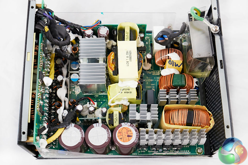
In the described power supply, you'll find voltages of about 340 volts DC, for two reasons. First, AC is measured in RMS, which is considerably lower than the peak voltage. I.e., 120 volts from the wall swings between -170 volts and +170 volts. Second, this power supply uses a voltage doubler, so you end up with 340 volts DC inside.
Doubling 120 to 240 is still mains voltage in my book, if a supply these days even does double.
Sure it's peak rather than RMS, but a warning that something "exceeds mains voltage" to me sounds like a description of a significantly bigger danger than that.
Ok, so this thread, with all the replies of people unaware of this in teenage years - seems to imply we should teach this stuff in schools early on. As teenagers are in general low on money and the most likely to try to repair something that get them back to gaming, while ignoring warning stickers ...
That's discharge + indication all in one. It's a great solution, elegant, effective, and one of my favorites. But you have to find the cents for the neon (usually) bulb.
Isn’t the AC side connected to the wall prongs? I touch/step on those all the time after unplugging things. Or is there something isolated from both the DC side and prongs where charge could be stored up?
Those big-ass black capacitors (470 uF each) are on the AC side. They are the bit that converts 230AC to 320DC, and they might keep their charge for some time.
Those are after the bridge rectifier, so there's no path for current to flow back out the plug from them. That also means you can't discharge them via the plug, of course.
I worked on electronics for the military, one of which was a giant 2000 Watt HF amplifier that was stock to a MRC-148. When we got new Marines one of the first things we'd show them was when you remove the cover, turn the lights off, and have a florescent light bulb nearby it will activate. The purpose was to demonstrate the distance which electricity, unabated can travel. That was followed by explaining:
- Always ground yourself to an actual building rod or a rod planted at least six feet deep.
- Lock out, tag out everything. Our tools were metal, go work on ONE truck with a battery array without an extension and you will almost certainly arc something.
- Voltage isn't what kills. It takes an insanely low amount of amperage to stop a heart.
- Always have another person nearby with a wood or rubberized object to disconnect the circuit. Being stuck being electrocuted is a surprisingly slow death that you will be entirely conscious for.
Or just short out the capacitor terminals with a metal object like the screwdriver and you're fine. But still, if you don't do that and you get chocked it will just be a little painful jolt.
You know, you'd think that would work, wouldn't you?
But dielectric soakage runs in reverse, too. So even if you short out the capacitor once, it can recover some voltage after days to months left open again. (The energy comes from the molecules in the dielectric relaxing, very slowly.)
This isn't a problem if the designer has put in a bleeder resistor across the capacitor. But some designers are cheap, and don't want to pay the extra few cents to make their products non-lethal to technicians. Some are just stupid (yes, dumbfuck "senior engineer" coworker, I am thinking of you here, you colossal waste of oxygen).
What you want to do is short it out, with a screwdriver or otherwise, then keep it shorted with a gator cable or even resistor. Then you'll be safe even if you set the project aside for a week. Or three months.
Had a pallet of military surplus capacitors, packaged as 3 big (soda can sized) caps on a blade frame and wrapped in conductive foil, plastic, then heavy paper. From the 70s and they were fine when i got them in 1997.
I wired up an unwisely huge bank out of them for some fun HV experiments. They were in a shed outside and could self charge to useful levels in the course of a windy day. Dont recall the actual numbers but it could vaporize dimes handily.
I tried some halfass "comb" antennas but wasn't seriously attempting to harvest static electricity to useful purpose. There's some "joule thief" circuits available cheap and easy now that make me wonder if its possible.
Dielectric absorption is a hazard for HV capacitors that are charged to over 1kV in normal use, since they can recover to dangerous voltages.
Mains filter caps will be lucky to recover a few dozen volts, which isn't going to do much (and inside a PSU, if the voltage is high enough it will try to run and quickly discharge them anyway.)
And yet, if the voltage is low enough, it will linger for minutes to hours. Plenty of time to kill someone.
Maybe I'm just salty about having had this argument too often recently. But I strongly believe that every mains voltage or higher system needs bleeders across its capacitors. If you don't want to pay for the resistor, fine... but leave the footprint for it.
This goes 10x stronger if the thing is open-frame, sits on a bench, and is regularly being probed by engineers. Just put the goddamn resistors in there before someone gets hurt.
I recommend against this. Most supplies have a bleed circuit, but if it doesn't or it doesn't work (at all or not fast enough), then shorting primary-side capacitors can make a really nice bang and also damage your "shortening implement". That bang can startle you and make you hit something. Been there done both. Not a great idea IMHO.
Check for voltage - If not present / marginal, Then shorten, Else discharge through resistor and GoTo Check. A "capacitor discharge tool" automates this cycle.
It requires some background in electronics. Personally I use gloves when working on electronics and soldering. There is nothing sophisticated about power supplies. Pressure vessels is where it gets real.
I had some contact with PSU designers at a name brand server company and learned some things:
1. Electrolytic capacitors: Only Japanese brands can be trusted (this sounds racist or something, but it's an actual requirement). They all should be de-rated for reliability (have 2x the voltage rating). Only exception is the main bulk filter capacitors, where your only reasonable choice is 450V, but these should be 105C. Tantalum capacitors: not allowed.
2. Main switch MOSFETs: only Infineon can be trusted. Single active clamp / single switch topology is a no-no due to bad experience. (I think the one in the article uses a diode clamp, so should be OK).
3. Standby supply needs its own fuse. The problem is that the main fuse is too big for the standby supply. If there is a standby supply fault, you will fill the machine room with smoke and your brand will be mentioned in the news when machine room is shut down. This destroys shareholder value.
The current limit for any exposed 12V rail is only 20A or something line that (240VA UL limit), so you must not have exposed 12V when the server cover is open.
There was basically a 100 page requirements document all along these lines.
Japanese brands are renowned for having a very reliable electrolyte formula. Dell sourced some capacitors made in Taiwan using a stolen copy of the formulae and it cost them massively.
Although even putting this aside, capacitors don't seem to age well - anybody interested in 80s/90s electronics and gaming, will be aware that they should check boards before plugging them in, and if in doubt, but a 're-capping' kit
An old school RF engineer told me you can put an incandescent light bulb in the enclosure for a few hours periodically to bake out the moisture and they are fine again. I was going to re-cap a 60s heathkit tube stereo and he asked me why I thought they had been fine for half a century but suddenly might blow any second? If you used the tube amps regularly the heat from the tubes kept the caps good.
Audio systems are usually powered off for most of the time. If it's on a couple hours a week, that 10 degrees increase might "boil off" that moisture while not making a dent in the capacitor lifetime.
Yes. Capacitors before around ~1990 used organic solvents and were, generally speaking, very reliable. Capacitors since then switched to water-based electrolytes, which are 1) much more aggressive which 2) leads to circuit board damage if they leak and 3) if done improperly has very bad longevity. Capacitor plague is basically all of these downsides combined in one sweet package: capacitors that fail quickly, and do so while leaking acid all over your circuit boards, acid which is strong enough to eat through solder resist, copper, fiberglass and even goes into IC packages, damaging them invisibly.
Old-timey capacitors with organic electrolytes are still available for applications that need reliability more than the best ESR or highest density, but they're kinda rare and expensive.
I would not be surprised if this trick was meant for early encapsulated foil capacitors. These were encapsulated in various semi-natural resins of not exactly known or repeatable properties (usually the intention was that the resin is hygroscopic, but often it was also porous and prone to cracking with aging).
Edit: then there is “RIFA plague”, which shows that you can get same issue even with better engineered encapsulation material.
Aside from outright "it popped and oozed all over the place" failure, you've got drift in specs-- the original design expected 100 +/- 10uF, and you're now at 60 or 125uF, with a different equivalent-series-resistance and leakage than the part had when new. In a lot of cases, this won't directly cause explosion, but it might make for a noisier signal down the line.
I've replaced the electrolytic caps in two different stereo recievers and one amplifier, all from the 1977-1980 era. Only one of the three had noticable difference in sound quality, but it was the one that had clearly been abused over the years (failing power switch that arced and sputtered, absolutely filthy and blown bulbs when I got it)
I can't tell you how many computers I replaced the mainboard for because of blown capacitors. Or the number of monitors I re-capped and brought back to life. It's a known thing in the LCD TV industry as well.
Some industrial espionage went wrong and a bad electrolyte formula was stolen, and of that's of course what manufacturers who were trying to save a buck (all of them for the most part) got.
Can't speak for the other aspects, but the capacitors issue was/is definitely a real thing. I know plenty of techs who spent weeks removing equipment due to faulty capacitors. Some of that equipment was worth having component swaps performed others were just junked / returned etc.
Nothing like "we're spending this whole month dealing with bulging or otherwise faulty capacitors" to raise eyebrows. As I recall it was a rolling wave of work done to mitigate multiple supply chain failures. "Just" because of capacitors.
Some components, mostly capacitors, have the wrong hole spacing for their pins, and leads were bent to fit. That suggests part substitutions during assembly. Many of the through-hole components were not pushed all the way down into the board. That suggests overworked assemblers. This was obviously hand-assembled.
The author makes a point that there's a clear division between the AC line side and the DC side. That's required for UL approval, but power supplies do show up without it. The power transformer that crosses the boundary should also have a split bobbin, so the AC line side coil and the output side coil are separated by a barrier, not wound on the same bobbin.
> The power transformer that crosses the boundary should also have a split bobbin, so the AC line side coil and the output side coil are separated by a barrier, not wound on the same bobbin.
Separate bobbin is not required for robust isolation.
For example, just right now on my bench there is a medical separation transformer. No separate bobbin (hint: it is toroidal).
There's worse power supplies sure but this one is still a mess. I don't see anything obviously dangerous but it's still a dirty ugly design and assembly. Other companies like Delta Electronics manage to cram lots of components in small spaces too but they actually do a good, clean job.
Most PCBs with large, heavy through-hole components are still manufactured by hand, by the way.
On a somewhat related note, I just found out johnnyguru, a major contributor to consumer psu reviews and knowledge, has shut down his site and forums. His tear downs were always fascinating
The computer enthusiast market is a difficult niche to cater to online. Most of the visitors will arrive with ad blockers enabled and they’re going to buy products from the cheapest retailer directly, not through affiliate links. Also, some of them will be brutally combative for no particular reason.
The originator of that website landed a dream job doing R&D for Corsair. The owner of the domain (not Johnny, as far as I can tell) simply decided to let it expire.
I tried a little earlier to bring up the site and DNS said SERVFAIL. Sigh. Oh well, that site pointed me the in the right direction regarding power supply choices.
> The secondary circuitry produces the four output voltages: 5 volts, 12 volts, -12 volts, and 3.3 volts. [...] The power supply also provides a negative voltage output (-12 V). This voltage is mostly obsolete, but was used to power serial ports and PCI slots.
And even older PC power supplies also provided a -5V voltage, the corresponding pin on the ATX connector is now (according to Wikipedia) a reserved pin.
This progression also shows in the expansion slot standards: the ISA slot had pins for -5V and -12V; the PCI slot removed the -5V pin; and the PCIe slot finally removed the -12V pin. That is, a motherboard without any ISA or PCI slot, and without a RS232 socket or header, has no use for the -12V voltage.
And there's already a newer power supply standard, called ATX12VO, which simplifies the power supply by providing only 12V (and a separate standby 12V). There's already at least one motherboard built for that standard: https://www.anandtech.com/show/15763/first-atx12vo-consumer-...
What prevents one from just wiring mobo.5v to port.gnd and mobo.gnd to port.-5v? That would effectively create a -5v potential between port.gnd and port.-5v
That would create a floating ground, and systems needs to be designed for it. Because likely motherboard ground is connected to chassis, and it connected to earth, while power supply most likely have it's own ground connected to earth.
-12 V was used for RS-232, which uses +12 V and -12 V levels (with a very wide tolerance band). Having a separate supply for this was a design decision which was pretty much instantly obsolete with integrated charge pumps: All RS-232 outputs are running off of charge pumps running at (-2) and (+2) ratios, so +-10 V levels with a 5 V supply.
I don't know what -5 V was used for. Maybe some analog circuits somewhere, very early MOS logic also often had awkward supply voltages (charge-pumps made this obsolete too, just like high-voltage supplies for EEPROMs).
Early DRAM chips like the MK4116 required -5 V, +5 V, and +12 V. (-5 was the substrate back bias for the chip.) So the ISA standard required -12 V, -5 V, +5 V, and +12 V.
I have a number of 80s and early 90s computers. They had some circuits that used ECL, which required a negative voltage. One I had to recently adjust had a power supply that outputted (when properly adjusted) +5V and -5.2V.
Then you'd also need a +10V supply for the port's +5V input, and to convert logical levels for communication between them. That would be trickier than just amplifying them because low/high of 0V/5V would become 5V/10V. Constant voltage offsets are generally a real pain.
Just an observation from years building computers. Never cheap out on power supplies. Always buy one (don't use one included in a case), and buy one rated 25-30% above what you think you'll need. Some of the most aggravating troubleshooting you'll ever endure can be avoided entirely.
Towards that end does anyone know if there any ATX power supplies that will stream out their sensor info over a serial port or something?
It'd be nice to have power monitoring on that side of the mainboard's power regulators and caps, to pick up marginal issues before they get filtered out, and the power supplies these days will have a little ucontroller with all that information anyway without the mainboard having to duplicate that monitoring circuitry in the right place.
For what's such an important piece of a computer there's so little introspection for data while in use that has to be being collected regardless. Yeah, you can always hook up a oscope or what have you, but catching it in the act of being marginal early on would have saved me more hours in my life than I'd like to admit.
I had a Corsair power supply with this feature. The system I built with it was quite flaky, but I could reproduce the failure and eventually debugged a 12V transient dropout (when running AVX workloads) that was the cause of the flakiness. The built-in monitoring didn't help at all; doesn't update frequently enough, and the computer crashed by the next USB polling cycle anyway. I used an oscilloscope.
I don't really have enough data to outright blame the power supply. I don't think I connected all of the 12V lines to the motherboard (power supply didn't come with enough cables), and I can't be sure that the motherboard was designed properly for a mildly-overclocked 6950X (VRM banks, capacitors near the CPU, etc.)
It was all enough of a pain that I will never buy another Corsair power supply. My current best practices involve only buying Seasonic power supplies, and connecting every possible "optional" power connector to the motherboard. If the PSU doesn't come with enough cables to do that, buy them separately. My current Threadripper motherboard has a 6-pin and 2 4-pin ATX12V connectors, and a Molex connector. Many are marked "optional" in the motherboard's instruction manual, but I have them connected anyway. Probably overkill. Great stability. Without having designed the system or the test scenario, skipping optional things sounds like the sort of thing that's going to cost you a lot of time at some random point in the future. Best to avoid, even if you look like an idiot to the EE that designed the board.
    $ sensors
    corsairpsu-hid-3-1
    Adapter: HID adapter
    v_in:        230.00 V
    v_out +12v:   12.00 V
    v_out +5v:     5.00 V
    v_out +3.3v:   3.00 V
    psu fan:        0 RPM
    vrm temp:     +49.0°C
    case temp:    +40.0°C
    power total:  96.00 W
    power +12v:   80.00 W
    power +5v:    16.00 W
    power +3.3v:   8.00 W
    curr in:          N/A
    curr +12v:     6.00 A
    curr +5v:      3.00 A
    curr +3.3v:    2.00 A
Server PSUs support such communication (looks like this is PMBus protocol, variation of SMBus, which is variation of I²C). In servers it's connected to the BCM and usually allows to read input and output power, FAN speed, temperatures and status (good/bad). The BCM often records historical data, including peak power (in last 1h, 24h), etc.
After quick searching is looks there are people reading this info with a MCU [1]. But I think it would be hard to find such PSU in ATX form factor.
Whenever I experience issues which are likely related to a power supply, it is much easier to drop in a known-good replacement than to spend time diagnosing the specific issues. Also better to remove a potentially faulty PSU before it damages much more expensive hardware.
The typical failure modes mean that it'll be marginal for a while, and should be able to give you information before it goes fully bad. Being able to have introspection before it goes fully bad is what I want, as I hope to have some data before it even makes it's way on to a bench.
The power clients (mainboard, GPUs, disk drives, etc) normally know they're getting pretty bad power from a PSU and filter it heavily to smooth it out. It'd be nice to know if the voltage is occasionally dropping and it's just being covered up by downstream caps that are over provisioned to just smooth out not fully rectified AC.
The data isn't necessarily collected. Many existing supplies use hardware counters or PWM modules to control the power output at a level very close to hardware.
There is no PID loop in the sense you mean. It's a hardware counter module that feeds a flip flop. There might be a free running ADC that is used to compare match against the counter module, or sometimes it's just a binary input like the AC signal zero crossing.
You don't need a CPU core to do this, and the older, cheaper parts do not necessarily have a CPU in them. There are even (iirc, very uncommon) designs with no digital logic save the switching.
I learned "what not to do" from my work experience, having to wrangle machines with cheap PSUs, and at home having a "supplied with the case" PSU say "pop" to me years ago. Get something good, and you won't have to get it twice.
But they don't last forever, and my old file server's 10-year-old PSU finally started causing random errors about a couple of months ago - recognized when a sustained hard disk operation dimmed the power LED. I had spares, but it's time for me to think about building something new. Whether it's more computing power for the same electrical input, or the same for less, I can do better.
They are not necessarily the cheapest ones, it is possible that the 400w is fine, the 550w is crap, and the 600w is fine again, even if they are in the same series.
They can also change the specs over time, without any indication on the packaging.
You have to look for reviews where they actually disassemble and check the insides of the psu to determine if it is a good buy.
There is a forum local to my language where they keep track of the small number of truly recommended models, there must be an English equivalent.
The 80plus sticker program doesn't mean a lot, but it does mean a little. Being from a brand that's been around for a long time and is not known for cutting all the corners helps too.
Random reboots, program crashes, kernel panics/BSODs, boot loops, and wavering displays are some of the things I've seen, aside from the system just not powering up.
Yeah, my old PSU would just shut down whenever I play an old game with vsync off. I’m thinking it couldn’t keep up with sudden power requirement. I recently replaced it with a better PSU and I’m not getting any of these shutdowns again.
> The 60-Hertz AC (alternating current) from the wall oscillates 60 times a second, but the power supply needs steady DC (direct current) that flows in one direction. The full-bridge rectifier [1] below converts the AC to DC.
And yet I learned something. In nearly 50 years of playing with electronics I've never seen such a beautiful LER (light emitting resistor).
Edit: I am disappointed in his hooking up his oscilloscope ground to some random point of the circuit. Did he really do that? It sure looked convincing on the video.
It's something that everyone using scopes learns not to do very early on. It can't be good for the wiring in the scope.
Its his style to feign ignorance, do something stupid, then explain what happened. He has a masters degree in electrical engineering and, well, does so much bad stuff that it has to be on purpose.
Though probably not due to current, likely someone took a torch to it to try to make it easier to remove, and then took a picture. Then again those connections are vastly undersized for the cables...
ATX12VO[1] is a proposed major change to PSUs that hopefully will come in the near future. It will mean simpler (cheaper) designs and improved efficiency. I hope that the DIY market adopts ATX12VO before my next upgrade. Currently only OEMs have the ability build PCs with these kinds of PSUs.
...which puts all the DC conversion on the motherboard.
Honestly, I can't tell if this is a good thing or a bad thing.
On the plus side, power supplies will be much simpler to design and test, with potentially better efficiencies.
On the other hand, all those additional DC-DC converters will take up quite a bit of space on the already crammed boards, and now you got more heat to manage.
It recognizes how things are already. The 5 V and 3.3 V step-down converters in the PSU are pretty much only for Molex/SATA-connected peripherals, and those don't use 3.3 V anyway (99.5 % of them), since it's not guaranteed to be there. So the 3.3 V rail is pretty much pointless. 5 V not quite as much, but even in an enthusiast-level PC there will be probably just a handful of things actually connected to that - most likely SSD/HDD and maybe something like a fan controller.
No heavy loads are connected to the 5 V / 3.3 V rails. Those are all supplied through the 12 V rail.
> The 5 V and 3.3 V step-down converters in the PSU are pretty much only for Molex/SATA-connected peripherals, and those don't use 3.3 V anyway (99.5 % of them), since it's not guaranteed to be there.
Yeah, not only is 3.3V not guaranteed to be there, the latest rev of the SATA power spec reused (at least one) of those pins as a signal to inhibit spin-up; used for power sequencing in large disk arrays, with the fun side effect that if you've got a PSU old enough to have 3.3v on sata power, and you use a hard drive new enough to support spin-up inhibiting, you need to either tape the pin, or cut the orange wire, or you can't use your disks.
Yes, there's actually a lot of stuff that uses 3.3 V, e.g. anything connected to smbus. But none of them connect directly to the PSU, so there is no need for the PSU to do it.
I remember reading about some people adding so much RGB stuff into their system to actually run into current (A) maximums on power supply 5V rail, so there might be some exceptions, though not many.
A modern supply would use the same principles, but would probably have mostly surface mount components, a single controller IC, and probably separate switching supplies for each different supplied voltage.
The power supply is from 2005. By my standards that's not very old, but maybe because I've also been looking at power supplies from the 1940s :-) Specifically a 100-pound Teletype power supply from the Navy that used mercury-vapor thyratron tubes.
Last time I looked at it it was not especially cost effective to build PC power supplies on multilayer boards. That leads to exactly the kind of construction as in this power supply: large almost completely through hole single-sided board with power components and one or more higher density perpendicular sub-boards with control logic.
2 layer boards with smd components are now cheaper than single layer and through hole - simply because through hole requires more labour to place components and has a substantially higher failure rate (bad joints).
Obviously some components in a power supply still need to be through hole for mechanical reasons, but it isn't many.
It is not that clear-cut. Obviously the optimal case is SMD-only, but there is a threshold when THT-only becomes cheaper than SMD/THT mix. Another thing is that power supplies tend to use higher temperature board material (presumably to allow for thinner copper plating) which is somewhat rare and expensive in dual layer configurations.
More than old, it is low-end OEM power supply. Even back in 2005 we already had stuff like 80 Plus ratings, active PFC, universal input, 600+ W output ratings etc.
I thought the same thing, how could there be no PFC? The UC3842B is not that old. [1] But I guess time has flown... The PFC requirement was part of Energy Star 5.0 which was 2009. [2]
Are you talking about a laptop power supply vs an ATX desktop power supply? Even most enthusiast ATX power supplies that I've seen don't use SMT for the main power board, probably because of the weight of the components.
I'm glad to see Ken's blog on HN. He does incredible stuff with reverse-engineering old proprietary chips, e.g. the HP nanoprocessor which he reverse-engineered from masks then wrote a disassembler for.
Nicely written up. It's not that complicated when you start to think about the different stages, and I think this walk-through breaks it up clearly.
If you continue further on to the motherboard, the CPU has a multiphase SMPS (sometimes exceeding 20 phases!) that drops the voltage further to core and IO voltages (usally ~1.8V or less for the former) but still has to generate lots of Watts (think about a Xeon or Ryzen at 3+ GHz).
What's really neat IMHO is how Apple changed the <5W adapter market by moving to dense SMP in such a brilliant form factor. It can take 120/240 because it is a buck converter and doesn't care about the input voltage.
I've wondered, if the SMPS circuit in the 5W apple adapters be scaled up to 600~800W would they be enormous and/or less efficient? Because it seems like the circuits in this board are either designed for higher power so big honkin' coils & caps are necessary, or are they that big (and inefficient) in order to save money?
> I've wondered, if the SMPS circuit in the 5W apple adapters be scaled up to 600~800W would they be enormous and/or less efficient? Because it seems like the circuits in this board are either designed for higher power so big honkin' coils & caps are necessary, or are they that big (and inefficient) in order to save money?
All power supplies of a few hundred watts will look broadly the same as this one. The rare exceptions are very expensive AC/DC modules[0], and linear power supplies used mostly in higher-end audio and test equipment.
There are a number of factors that influence the designs that are practical for different power outputs but a big one is the gate charge of the switching transistor. Bigger output power requires a bigger switching transistor which stores more charge in its gate. This requires more energy from the controller to charge and discharge the gate and more concern about the ohmic losses in the transistor as its transitioning from being on to being off. This limits the switching frequency you can practically use. Lower switching frequency means larger transformer; you need more iron to take the magnetic field so it doesn't saturate on the larger slower pulses.
Note also that with more power almost every component needs to be larger. Also note that standard PC supplies need to supply many voltage rails while the classic Apple 5W adapter only needs one. With newer standards like ATX12VO the supply only supplies 12V and 12V standby.
I'm still boggling at the way that power is not conducted electrically across the power supply but is instead air-gapped and pass magnetically, via transformers.
Isn't that a lot of power?! A modern PC can easily draw 500W or more. Does that mean there's some enormous magnetic field in my power supply? Why doesn't that pose a problem for the things around it?
(I cheerfully admit to being very very good at manipulating bits, CPU opcodes, and TCP/IP packets and knowing next to nothing about electrical engineering.)
The magnetic field is mostly confined to the core of the transformers, so your power supply isn't going to start attracting things like a giant magnet. This internal field is pretty strong, though, up to 0.3 Tesla in a ferrite core. In comparison, a refrigerator magnet is 5 millitesla and the Earth's magnetic field is 30 microtesla.
The magnitude of the magnetic field is small and mostly conducts through the ferrite for maximum efficiency; it's the frequency which allows so much power to be conducted.
Also almost nothing in your computer is affected much by moderate magnetic fields. Go ahead, stick magnets all over the motherboard!
Air-gapping is a nice side effect, but the real point of using transformers is that they trivially transform voltage. Altering voltage by resistance is enormously wasteful, and can only lower it. Altering voltage by quickly turning it on and off (PWM) only works with certain inert types of load, like electric motors; it works for LEDs only because the inertia of the eye. But this is close enough to AC anyway.
Also, the energy of an electromagnetic wave grows as the 4th power of its frequently, IIRC. This is why old power supplies which directly used the 60Hz frequency from the socket were so bulky, while modern power supplies, which convert the mains electricity to high-frequency AC, can use physically small and lightweight transformers.
> Also, the energy of an electromagnetic wave grows as the 4th power of its frequently, IIRC. This is why old power supplies which directly used the 60Hz frequency from the socket were so bulky, while modern power supplies, which convert the mains electricity to high-frequency AC, can use physically small and lightweight transformers.
It's much more roundabout than that.
A transformer has a magnetizing inductance (you can measure this with an LCR meter by leaving all other windings open). This is generally a pretty big inductance (several henries for mains transformers). When you supply a waveform, that inductance will cause a small current to flow. That's the magnetizing current. The problem is saturation - if the voltage over time gets too large [=the magnetic field in the core], the transformer's core will saturate (that's also why transformers cannot handle DC; any DC offset will accumulate over time and cause saturation). This causes the magnetizing inductance to drop to approx. zero. When that happens, the magnetizing current becomes huge, basically a short circuit.
This means that you need to avoid saturation. Note that the strength of the field depends on the number of turns - each turn reduces the impressed field. So you want as many turns to avoid saturation as necessary, but as few turns as you can get away with (each turn adds resistance, and needs space inside the transformer).
And this is why mains transformers are so big. Because the frequency is low, voltagetime is large. So they need many, many turns (a few hundred to thousands) in order to prevent their steel cores from saturating. So the primary winding is a very long wire, which has a lot of resistance. So you need to increase the size of the core to fit a thicker wire, in order to avoid resistive losses. Now that bunch of wire doesn't fit any more through your transformer, so you need to use a bigger core, but wrapping N turns around that needs even more wire and so on. So you end up with a big, heavy transformer.
For a high-frequency switch mode power supply, the frequency is high, so voltagetime is orders of magnitude lower (e.g. 100 kHz vs. 50 Hz = 2000x lower), so they need far fewer turns. So their primary winding's wire is short, so it can be a) a little bit thinner and b) takes up much less space! So you get a small, light transformer.
But the core, it doesn't really care about power, like at all. It's all about not driving it into saturation, and having windings that can carry your current. Those two factors make the cores of mains transformers so big.
Minor point on last bit, the core does care about power. The magnetic flux carries energy over time.
Saturation for mains transformers is not usually an issue but there are a fair number of electronics that could be made smaller with materials supporting higher magnetization.
Server power supplies are impressive. I pulled out some PSUs from old scrapped servers. In a smaller form factor than ATX they deliver more than 1kW power. You read that right. 100A at 12V actually.
If anyone wants to see a really top quality PC power supply, for comparison to a cheap one, take a look at the board and layout on a $100 seasonic power supply. Well known Taiwanese power supply company that doesn't try to compete on cheap prices and has been around for 20+ years.
The real treats were the bottom-of-the-barrel PSUs. I remember having to deal with a slew of these at work back in the early aughts. I remember turning on a machine one day... sssFWSSSSSSSHH and the magic smoke came pouring out. It would up taking out the the motherboard and hard drive with it. I autopsied the dead power supply, and it was chock full of capacitors (some blown-out) marked "Rulycon" (note, not Rubycon).
As I recall, the Apple II was fairly advanced for having had a switching power supply. I understand in fact it was practically unheard of in consumer electronics.
I know the Apple I was a kit and came with no power supply but every one I've ever seen the hobbyist has added a clunky linear power supply with a monster transformer and giant electrolytics.
It's almost like the two computers stood so near but just across from one another on two sides of some threshhold.
As I recall, early switching power supplies could not pass FCC Part 15 compliance for home use. This was in part because adding the necessary shielding added cost, and in part because the switching supply was typically more expensive than a gigantic transformer and a linear voltage regulator.
The link you found explains it well, but there is a different perspective if you want to focus on impedances. The idea is to drive the capacitor with a high impedance. This impedance should not be a resistor, because a resistor will limit current (more current means a higher voltage drop in the output), further it will consume power and become hot. Instead, you should look for something that works more like an ideal current source. An ideal current source has an infinite output impedance (because loosely speaking the impedance R=dv/di and di=0 for an ideal current source). A constant current source is a good fit for charging a capacitor since a constant current means a constant dv/dt slope. Now, as your link shows, a switching power supply does not have a constant current source in its main circuit, but it does use an inductor which has similar characteristics since inductors resist changes in current. The governing equation of an inductor is v=L*di/dt, and for the output impedance of the inductor you get loosely speaking R=dv/di =L/dt, which is large for large L and short timescales (dt close to 0), hence the similarity to an ideal current source. Now the driving part of the circuit at the left of the schematics in your link is a voltage source. So to drive an inductor, you use a voltage source. And to drive a capacitor, you use a current source. Inductors can be seen as current sources, and capacitors can be seen as voltage sources. I hope this explains it.
I never realized the main transformer element worked on rectified AC. Could someone explain why we rectify the AC power before the transformer? I always thought transformers worked on AC power anyways.
50/60hz requires a large transformer core. Switching power supplies rectify to DC, then drive the transformer at potentially megahertz which increases efficiency and substantially reduces the size and weight of the core. For similar reasons aircraft use 400hz 115v supply as it makes all of the power conversion electronics dramatically smaller.
A transformer converts electrical energy into a magnetic field and back into electrical energy. All the energy from a single 'sine wave' must be stored in the magnetic field inside the transformer briefly before coming out of the output. The transformer core is made of steel usually. For a given weight of steel, there is a maximum amount of magnetic energy it can store.
That means that at low frequencies like 50/60Hz, transformers end up very bulky.
Wasn’t immediately clear from GPs comment and my admittedly limited physics instruction, but the way you explained it made it seem incredibly obvious in retrospect, which is a rare skill, thanks!
I think they are asking this: why not use the transistor to chop the 50/60 Hz AC into potentially-megahertz AC? Then pass that chopped AC to the transformer, which could still be small.
The motivation would be to try to eliminate the full bridge rectifier and the high-voltage capacitors.
I'm not an EE, but I would guess the simple answer is it's because you can't pass a AC through a transistor, since a transistor not only switches but also acts like a diode.
I think you could work around that (build a circuit that switches AC with transistors), but there must be a reason why you wouldn't want to. Perhaps it's because it's simpler to just go ahead and rectify, or perhaps there's an advantage to having capacitors on the high-voltage side.
There are two stages: power factor correction, and the forward converter. The forward converter uses a transformer mainly for isolation. The power factor corrector exists because the transformer is an inductive load. If you have too much of an inductive or capacitive load on a distribution network you affect is performance.
You can make the power factor corrector, which does the rectification, out of active components that switch in time with the AC signal. This eliminates the voltage drop of the diodes which can be a few percentage points of efficiency and a fair bit of heat.
If you didn't need to isolate the power supply you could chop mains directly but you need to manage the radiated noise. The current designs try to maximize safety and then economy and then efficiency. Coincidentally, the power factor correction, done correctly, also helps reduce radiated noise by keeping the system synchronized with the incoming power. (This is not precisely accurate but is an interesting way to think of it.)
One problem is that when your 60 Hz AC goes to 0, your chopped AC will go to 0 too. You'll need to store energy somewhere to get across the milliseconds of no power. And your transistor, transformer, etc will need to be larger to handle the peaks.
Circuit that tries to do this directly from AC is going to be more or less equivalent to active rectifier followed by traditional SMPS power stage (including some kind of DC bus with some nontrivial smoothing capacitor). In case when the whole thing is only supposed to work in one direction and input is low fixed frequency AC such construction is simply not worth it.
Nowadays it’s not an issue as much since the advent of digital seat-back entertainment but often, listening to analog passenger aircraft audio loops you can hear the 400Hz come through. 400Hz is noticeably sharper than G but between G (392 Hz) and G# (415 Hz) on the standard musical scale (A = 440Hz). So the 400 Hz clashes with everything.
Hey Ken! Thanks. Yep that spec (dated 6 October 1959) says:
4.1.1 A-c power. The a-c power system shall be a 3-phase, 4-wire “Y” system, having a nominal voltage of 115/200 and a nominal frequency of 400 cps. The neutral point of the source of power is connected to ground (see 3.2), and the ground is considered the fourth conductor.
and
5.1.5 Steady-state frequency. The a-c power systems frequency shall be maintained at 400 ± 20 cps for steady-state operation.
The standing field in a massive 60Hz transformer also necessitates robust inrush protection. With a transformer across the mains, losing the input power momentarily can cause a huge surge current when the input is reapplied. With the bridge and filter first, the inrush from being momentarily switched off won't be severe.
In switching mode power supplies like this, the mains AC is rectified and then chopped up into higher frequency pulses and fed to the transformer. The higher frequency allows for smaller transformer. It also allows for voltage regulation because the input pulse width (in this case via the UC3842B controller IC) can be altered based on the sensed output voltage.
I built some 50Hz transformer power supplies when I was younger. :) They were 2x the size of the ATX power supply, produced like 60-100W of power, and weighed something like 2kg. Friends building class A audio amps were quite fond of toroidal transformer power supplies, too.
They are easy to build, much less complex than switching power supplies. But as others say, less efficient and I'd guess more expensive, these days, unless you have some spare toroid transformer and high capacity low voltage capacitors laying around, already.
Just the toroidal transformer for the 800W power supply would weigh like 8kg or so. :)
That's exactly what I did for my first benchtop supply. Being a student, 'free' was a pretty good deal. Used it regularly for a good many years until one project I had drew so much current it really accentuated the voltage ripple.
Be careful though, ATX power supplies don't have a crucial feature that bench supplies do: setable current limits. They will pump out as much power as they can to maintain the output voltages until they saturates.
Which can result from releasing some magic smoke if you are lucky, to a call with your insurance company.
There are losses in every step, and power supply design is basically a big optimization problem to choose all the design parameters to minimize losses.
The main components with losses:
* The input capacitors are non-ideal and have some resistance. That resistance causes heat every time current flows in or out of them.
* The MOSFET switch has an 'on resistance' which means it wastes energy when current flows through it.
* The MOSFET takes a certain time to turn on or off. During that time it is partially on, which wastes a bunch of energy each switch.
* The transformer has resistance in the coils.
* The transformer has iron core hysteresis, which makes the steel of the transformer get warm as magnetic fields change in it.
* The diode on the output side has voltage drop across it.
* The capacitor on the output side has resistance.
It was a real learning experience moving from ideal transistors to real MOSFETs in an H-bridge driving a motor. Gate capacitance led to lots of expensive smokefests.
They do help. Since HN finds it interesting I can write some on the most modern designs. I am currently designing a FOSS power supply. One of the goals is to go for high efficiency. The end product will use GaN and SiC elements. The different chemistries give different switching characteristics. (Interesting aside is that some topologies can run forward as line conditioning AND backwards as a motor inverter.)
There are also supply chain and security considerations, though. You can buy magic PSU chips but what if you can't?
Goal is to make it [optionally] smart, compact, modular, and ATX compatible. Hopefully with just the newer 12V standard. My original motivation for the project was lack of SMBus/PMBus support on desktops (on a laptop, it's the battery controller that allows you to see power usage).
I just started putting myself out there. I have material queued up that I need to edit and I need to pick out the good parts for blog posts. I've started acquiring components for the prototypes. Sadly it's slow going, HW prototyping is kind of expensive for me right now. My design progress is way ahead of what I've actually documented and I need to start documenting so it looks better.
After some searching I've found that Supermicro is selling ATX power supplies with SMBus (hopefully PMBus really) connection in reasonable price but never had one and I'm not able to find any review.
I'm kinda surprised there would be still significant margin in improving efficiency, considering that modern top tier PSUs are already 90-95% efficient
You are right, power supply improvements are asymptotic. It's not just about total efficiency, but also about how the heat is generated and where you can put it. A lot of the newer developments don't do a lot for total efficiency but produce smaller supplies by more efficiency managing heating.
That said, most supplies for sale are based on old, fossilized designs created ~10 years ago, hovering at around 80%. If you spend more you can get the gold, titanium, etc. But then, even those tend to be below the maximum you can get, which is closer to 98% if you have information about your load. You can also design the system to have better efficiency at various loads. Typically half, but could be worth tracking newer CPU/mobo/GPU developments.
The big improvement is you can get the same performance in a smaller space. This either lets you go more efficient (and the difference between 90% and 95% efficient is halfing the amount of heat to get rid of) in the same space or smaller for the same efficiency.
I would suspect that it is simply the subtle art of pushing components closer to their limits... since a laptop is unlikely to be drawing 170W continuously, they may be using PSUs with the same peak ratings but at a lower duty cycle.[1]
(Note that Lenovo itself almost certainly doesn't design nor produce them -- if there's a UL registration number or similar, you may be able to find the actual OEM/ODM.)
[1] You can see something similar in the marketing specs for cars vs. trucks - a performance car may have a 2L engine rated for 300HP, while you can find a truck with a 9L engine also rated at 300HP. The former is unlikely to last for long putting out its rated power.
While possible, high frequency microcontrollers and better capacitor technology (especially extremely low esr hybrid electrolytic capacitors) allow much better efficiency than was previously possible. Component costs have been driven down by wider adoption of inverters too.
Electronic speed controllers for brushless motors are one area you can really see this too - they are amazingly compact, efficient, and high power now.
Exactly. GaN FETs are slowly taking hold of the market, due to their ridiculous performance capabilities (mainly being able to switch much faster than silicon for the same losses). I think there was a car manufacturer who reckons there would eventually not be any silicon power transistors in their vehicles, they would all be either GaN (for lower voltages) or SiC (for higher voltages).
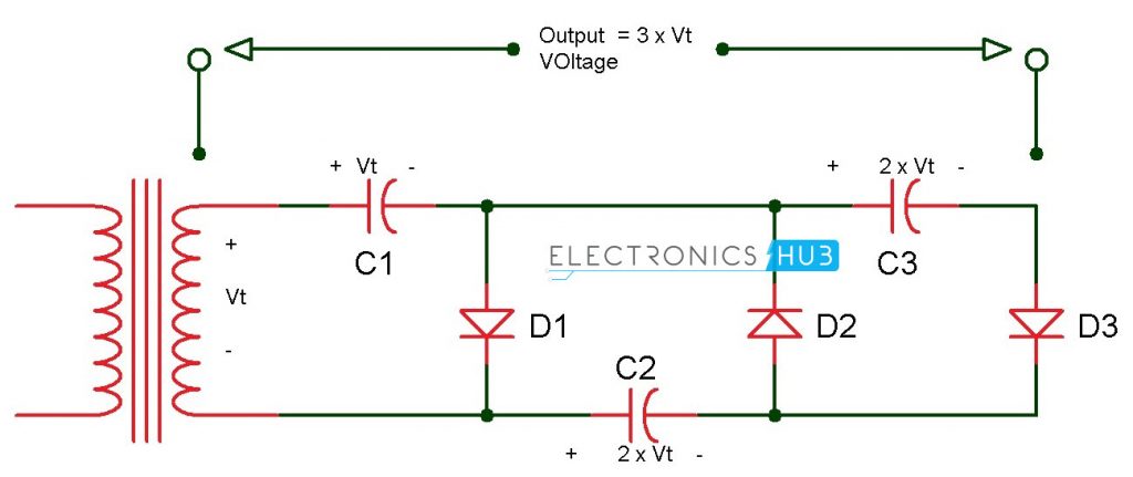
Isn't there a way to create a rectifier with just three diodes? I remember having come up with a way to make one once, but there must have been something wrong with it (I know nothing about electronics). Now I can't remember how it was, or maybe it had 4 and just looked slightly different from the typical one.
As a matter of fact you can do it with just one... That would be a half wave rectifier (not that good, you miss half the cycle). You can also do full wave with just two, but you need a center tap on your transformer. I remember finding both of these in early guitar tube amplifiers schematics (those early ones used vacuum tubes for everything: rectification, pre-amp & power).
Yes, there is. 3 diodes and 3 capacitors. But the catch is that the output is going to be 930 Vcc instead of just 310 Vcc. It's called Vcc multiplier and you can easily reach thousands of volts this way - that's how the police teasers work, they have a small DC to AC converter and then use this kind of multiplier to shock people by driving 25K Vcc, but the intensity is around 10 nA (if it would be 1 mA the teaser would kill instantly).
The description of the regulation of the 3V3 circuit is IMHO misleading. The inductor isn't a magnetic amplifier (multiple coils would be needed), but rather a filter element.
Are you familiar with the use of magnetic amplifiers to regulate 3.3 V outputs? I traced the circuit and it's a magnetic amplifier. The same winding is used for control and output, as is typical in power supplies.
Although called a magnetic amplifier; this application really
uses an inductive element as a controlled switch. A mag
amp is a coil of wire wound on a core with a relatively
square B-H characteristic. This gives the coil too operating
modes: when unsaturated, the core causes the coil to act
as a high inductance capable of supporting a large voltage
with little or no current flow. When the core saturates, the
impedance of the coil drops to near zero, allowing current
to flow with negligible voltage drop. Thus a mag amp
comes the closest yet to a true "ideal switch" with significant benefits to switching regulators."
In most other parts of the computer the worst that can happen in most cases is that you damage the computer, the power supply is different, there you also have a good chance of getting shocked.